3D Printed Brackets and Mounts: How They Carry Load and How to Design Them
Where printed brackets and mounts fail and how to design against it: orientation, fillets, ribs, walls, fasteners, creep, heat, material choice and testing.
The Short Answer
A printed bracket fails where the load meets a weakness of the process: across the layers, at sharp inside corners, around holes and fasteners, and over time under a constant load or heat. Design against each one: keep the main load in the layer plane, fillet every inside corner, add ribs where stiffness is needed, spread fastener clamp load through washers or metal sleeves, and choose a material whose datasheet supports the temperature and humidity at the mounting point. We do not give load ratings for printed parts. A bracket or mount whose failure could hurt someone, such as one holding weight overhead, near people or on a vehicle, needs your own engineering and testing before it goes into service.
Follow the Load Path
Trace the load from where it is applied to where the bracket is fastened. In an L-bracket or a cantilevered mount, the bending moment is largest at the root, where the arm meets the base, and that is usually where the inside corner, the layer boundaries and the fastener holes sit too. Most of the design effort belongs at that one spot.
| Failure mode | Where it starts | Design response |
|---|---|---|
| Layer separation | Bending or tension across layers | Orient so the load runs along layers |
| Corner cracking | Sharp inside corners | Fillet at about half the wall |
| Hole and joint failure | Thin walls, plastic under a bolt | Bosses, washers, metal sleeves |
| Creep | Constant load over weeks | Design to creep data, test over time |
| Softening | Hot locations, sun, motors | Check the grade's heat data |
Keep the Main Load in the Layer Plane
An FDM part is built from fused beads, and NIST researchers describe the strength of such a part as limited by the weld between layers. One maker's datasheet shows the size of the gap for one grade: Polymaker lists dry, annealed tensile strength of 109.3 MPa in X-Y and 54.0 MPa in Z for its Fiberon PA6-CF20. Those are the manufacturer's datasheet values for that grade on its own specimens, not ratings of a part we print. For a bracket, the rule is to orient it so that bending stretches the beads along their length instead of pulling layers apart. An L-bracket printed with its L profile flat on the build plate keeps both legs and the corner within layers. Printed standing on one leg, the corner's layer boundaries take the full bending load. Our print orientation guide covers more cases. When the load runs in several directions, say so when you order, because orientation is one of the things the free printability review checks.
Fillet Every Inside Corner
DuPont's design guide for engineering polymers calls sharp internal corners and notches perhaps the leading cause of failure of plastic parts: stress rises abruptly at the corner, and most plastics are notch sensitive, so cracks start there. Its general rule, drawn from stress-concentration data for a cantilevered beam, is a fillet radius equal to half the wall thickness, with very little further gain from a larger radius. The guide was written for molded parts, but stress concentration is a matter of geometry, so the rule is a sound starting point for a printed bracket.
- Fillet the root of every arm, the base of every rib and the transition into every boss. A sharp corner in the model prints as a sharp corner.
- In FDM, a fillet that spans layers is built as a series of small steps, and the layer boundaries at the corner remain the weak plane. Orientation and the fillet work together; neither replaces the other.
Ribs and Gussets
DuPont's guide notes that ribs can greatly increase the section stiffness of a simple beam, because rigidity is proportional to the moment of inertia of the cross section, and that a ribbed section can replace a thick one with less material. It also warns that ribs can introduce stress concentration, and advises leaving questionable ribs off the drawing and adding them if prototype tests show they are needed. For a printed bracket:
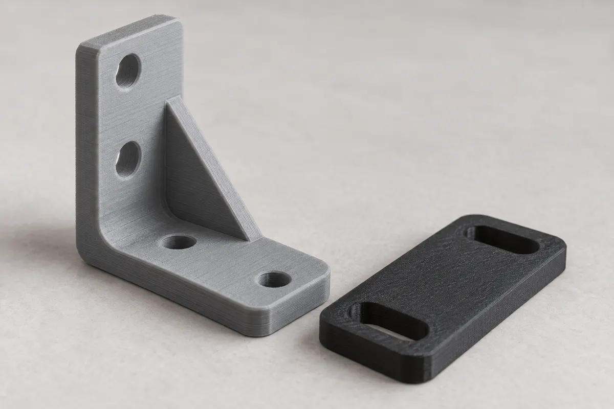
- A triangular gusset between the legs of an L-bracket puts material far from the bending axis, which is where it adds the most stiffness. Fillet both ends of the gusset.
- Run ribs in the direction of the bending stress, and where you can, orient the part so the ribs lie within layers.
- Molding guides size ribs at a fraction of the wall (DuPont gives one half to two thirds) mainly to avoid sink marks and distortion at the rib's base, which are molding defects. Treat that ratio as a starting point for a printed rib, not a rule it must follow.
Walls, Perimeters and Infill
Bending stress is highest at the surfaces of a section and lowest near its middle, so in an FDM bracket the perimeter walls carry most of the bending load and sparse infill carries little. That is why wall count usually matters more than infill density for a bracket; our infill guide explains the trade-off. Material datasheets are printed differently from most parts: Polymaker's specimens for the grades cited here are printed fully solid, so a sparsely filled bracket should not be expected to reproduce datasheet numbers.
- To make a bracket stiffer in bending, ask for more perimeter walls before more infill.
- Ask for solid material around holes, inserts and the root of each arm.
- If a test or approval depends on particular build settings, state them. If not, keep them identical between the brackets you test and the brackets you deploy.
Holes, Fasteners and Clamping Into Plastic
A bolt holds a printed bracket by squeezing the plastic under its head, and plastic does not hold that squeeze. DuPont defines stress relaxation as the decay, over time, of the stress needed to hold a fixed deformation, the same phenomenon as creep. SPIROL, which makes compression limiters for bolted plastic joints, states that plastic always exhibits stress and strain relaxation under even modest loads. Design the joint so the clamp load goes through metal:
- Spread the load under the head with a washer or a flanged bolt.
- For a joint that must stay tight, use a compression limiter: a metal sleeve slightly shorter than the plastic is thick. Once the bolt seats on it, SPIROL explains, the limiter takes further clamping load without further significant compression of the plastic. DuPont's guide similarly suggests metal rings under the bolts to reduce creep at a bolted plastic joint.
- Give each hole a boss. DuPont's rule for molded parts is an outside diameter of two to three times the hole diameter.
- Where a screw is removed and refitted, use a metal threaded insert. Our threaded inserts guide covers hole sizes and installation; insert installation is an FDM post-processing option quoted on request.
- Where a printed bracket bolts to metal and sees wide temperature swings, allow for movement. DuPont notes that unreinforced plastics can expand six to eight times as much as most metals. Slotted holes let the joint move instead of loading the plastic.
Creep: A Constant Load Is a Different Load
A shelf bracket, a sensor mount or a cable hanger carries its load all the time. DuPont's guide describes what follows: a plastic part deforms the instant a load is applied, then continues to deform at a slower rate while the load stays on. That additional deformation is creep. The guide's consequences for design:
- Short-term strength and modulus are the wrong numbers for a sustained load. DuPont calculates long-term deflection with a creep modulus taken from creep curves, not the elastic or flexural modulus.
- Heat accelerates creep. DuPont adds that knowing the maximum temperature is not enough; the total time spent at that temperature matters too.
- Intermittent loads are kinder. A part unloaded between uses recovers to some extent, depending on the stress, the time under load and the temperature.
- Moisture changes nylon. Polymaker's datasheets show it for two grades after the conditioning they describe (immersion in water at 60 °C for 48 hours, harsher than ordinary humidity): the X-Y tensile modulus of Fiberon PA6-CF20 falls from 8636.5 MPa dry to 2508.1 MPa wet, while Fiberon PA12-CF10's falls from 3311.2 MPa to 3131.7 MPa. Those are the manufacturer's values for those grades. Our nylon conditioning guide explains the effect.
- None of the filament datasheets cited here includes creep curves. For a constant load, ask the material's maker whether creep data exists, keep sustained stresses low, and test the bracket under its real load and temperature for as long as your schedule allows.
Heat
Heat deflection temperature (HDT) is the heat figure most datasheets offer, and it is easy to over-read. ASTM D648, a standard HDT test, describes itself as particularly suited to control and development work and says its data are not intended for use in design or for predicting endurance at elevated temperatures. Use HDT to compare grades, then test the bracket at temperature. Datasheet values also depend on how specimens were made: Siraya Tech's datasheet for its Fibreheart PPA-CF Core lists HDT at 1.80 MPa of 84 °C unannealed and 126 °C annealed, the manufacturer's values for that grade. If a heat figure you rely on assumes annealing, put that in the specification so it can be reviewed. Our heat-resistant materials guide compares the options.
Choosing a Material
Match the material to the mounting point first and the load second. Each catalog grade has a page in our materials catalog.
| Material | Why consider it | Watch for |
|---|---|---|
| PETG | Indoor brackets, moderate loads | Lowest heat deflection of these |
| ASA | Outdoor and sun-exposed mounts | Check heat at the location |
| PC | Warmer spots than PETG or ASA | Maker advises annealing after printing |
| PA12, PA12-CF | Humid or oily locations | Less stiff than PA6-CF when dry |
| PA6-CF | Stiffness where deflection matters | Stiffness falls as it absorbs water |
| PA6-GF | Stiff mounts, smaller Z gap in one grade | Absorbs moisture; check wet values |
| PPA-CF | Hot locations | Heat values depend on annealing |
Where Those Reasons Come From
The table draws on manufacturers' datasheets for specific grades. Polymaker lists HDT at 1.8 MPa of 74.8 °C for PolyLite PETG, 100.2 °C for PolyLite ASA, 107 °C for PolyLite PC, 157 °C for Fiberon PA6-GF25 and 173 °C for Fiberon PA6-CF20. It describes ASA as an alternative to ABS with improved weather resistance and UV resistance, and recommends annealing PC parts right after printing to release internal stress. It describes PA12-CF10 as less moisture-sensitive than PA6-based materials, and Evonik describes its molding-grade PA12 as resistant to oils, greases and fuels, with extremely low water absorption. For PA6-GF25 it lists dry tensile strength of 80.1 MPa in X-Y and 60.7 MPa in Z, a smaller gap between directions than its PA6-CF20 figures above. These are the manufacturers' values for those grades on their own specimens, and every one of these sheets says its typical values are for reference and comparison only, not for design specifications. Our catalog grades may come from other makers with different values, so treat these as a comparison of families and confirm the grade with the team when a number matters. See PETG, ASA, Polycarbonate, PA12-CF, PA6-CF, PA6-GF and PPA-CF. Most structural brackets are FDM parts; for small, detailed mounts, our engineering SLA resins guide compares the SLA options.
Test the Bracket, Not the Datasheet
Polymaker's datasheets say their values should not be used for design specifications, and DuPont's guide advises prototyping the part and testing it in the end-use application. For a bracket, that means:
- Test brackets made exactly the way the deployed ones will be: same material, orientation, build settings and finishing.
- Load them the way they are loaded in service, including the sustained load and the temperature, not only a quick pull to failure.
- Test more than one, and order spares for destructive tests. Quantity pricing tiers apply automatically on the quote.
- Write the build into the specification so deployed parts match tested ones. Our guide to specifying printed parts for validation testing lists what to state.
- Where failure could injure someone (weight overhead, a mount on a vehicle, a part under pressure), the engineering and testing are yours. We build to the specification agreed on the quote; we do not rate printed parts for load, run simulations or certify parts, and the free printability review checks printability, not fitness for the job.
Before You Order: Bracket Checklist
- Load direction marked on a drawing view, with any feature that must not be loaded across layers.
- Every inside corner filleted, including the roots of ribs and bosses.
- Bosses at holes, and washers, metal rings or compression limiters wherever a bolt clamps plastic.
- Threaded inserts named by manufacturer part number where screws are reused.
- Material chosen for the temperature, sunlight, humidity and chemicals at the mounting point.
- Constant loads identified, with a plan to test under sustained load at temperature.
- Process, material and color set per part on the quote. One order can mix FDM and SLA parts.
- Free printability review requested: tick Engineering / DFM review when you enter your contact details.
- Part number and revision in the file name, so tested and deployed brackets match. Then upload the files for an instant price.
Frequently asked questions
How much weight can a 3D printed bracket hold?
Which way should an L-bracket be printed?
What material should I use for a printed mount?
Will a bolted printed bracket loosen over time?
Can you test or certify my bracket?
Sources
- DuPont: General Design Principles for DuPont Engineering Polymers, Module I (hosted by Stellenbosch University)
- SPIROL: Compression Limiters for Plastic Components (catalog and design guidelines)
- NIST: Thermography and Weld Strength Characterization of Thermoplastic Extrusion 3D Printing
- ASTM: D648-18 Standard Test Method for Deflection Temperature of Plastics Under Flexural Load in the Edgewise Position
- Polymaker: Fiberon PA6-CF20 technical data sheet V1.1
- Polymaker: Fiberon PA12-CF10 technical data sheet V1.1
- Polymaker: Fiberon PA6-GF25 technical data sheet V1.1
- Polymaker: PolyLite PETG technical data sheet V5.2
- Polymaker: PolyLite ASA technical data sheet V5.1
- Polymaker Wiki: PolyLite PC technical data sheet
- Siraya Tech: Fibreheart PPA-CF Core technical data sheet
- Evonik: VESTAMID polyamides
Upload your bracket for review
Upload the bracket, choose its material and mark which way the load goes. Ask for the free printability review of walls, orientation and material before you order.
Upload your bracket