How to Specify 3D Printed Parts for Engineering Validation Tests
What to put on the drawing or PO for printed test parts: material grade, orientation, build settings, tolerances, finishing, conditioning and revision control.
The Short Answer
Write the specification so that anyone reading it would build the same part: process, material grade, build orientation relative to the load, layer height and FDM walls and infill where the test depends on them, critical dimensions and tolerances, finishing, conditioning, inspection and the file revision. Those are production parameters, and we build to the specification agreed on the quote. Whether the part meets its load, temperature or life requirement is what your test decides, because a printed part's properties depend on how it was made. Send the specification with your files so it is reviewed before anything is built.
A Specification Is Not a Validation
A specification says how the part is made. Validation shows whether that part, made that way, does its job. ASTM D638, the common tensile test for plastics, notes that tensile properties vary with specimen preparation and that a material cannot be tested without also testing how it was prepared. Material datasheets carry the same warning. Polymaker's datasheet for its PolyMide PA6-CF filament says its typical values are for reference and comparison only, should not be used for design specifications, and can vary significantly with printing conditions. A test of a printed part is therefore a test of one material, one process and one set of settings together. Change any of them and the result may no longer apply. Our side of that line: we offer a free printability review, in which an engineer checks walls, tolerances, orientation and material choice at no cost and with no obligation to order. That review is not engineering validation. We do not run simulations, certify parts or promise a test outcome. Your test plan owns the pass or fail.
Material Grade and Process
- Name the catalog grade, not the family. Nylon could mean PA12, PA12-CF, PA6 or PA11, and they behave differently. Resin could mean Standard, Tough or High-Temperature. The materials catalog lists every grade by name.
- Name the process: FDM or SLA. One order can mix both, and each part is configured and priced by its own process and material, so a test that compares them can be a single order.
- Fix the color for builds you intend to compare, so a variable you did not mean to change stays the same.
- If a pass criterion comes from a datasheet, attach that grade's datasheet to the specification so everyone compares against the same document.
Orientation: Say Which Way the Load Goes
FDM parts are built from fused beads, and the bond between layers governs strength across them. NIST researchers describe the strength of a part made by fused filament fabrication as limited by the weld between layers. A Texas State University study of printed ABS specimens found build orientation significantly changed compressive and flexural strength, and its authors note that a printed part is stronger within a layer than across layers. One maker's datasheet shows the size of the gap for one grade: Polymaker lists tensile strength of 105.0 MPa in X-Y and 67.7 MPa in Z for PolyMide PA6-CF, annealed and dried. Those are the manufacturer's datasheet values for that grade on its own specimens, not a rating of any part we print. Our orientation guide covers the design side.
- State the load direction on a drawing view and name any feature that must not be loaded across layers. If you require a particular build orientation, give it relative to the part's datums.
- Report orientation with a standard convention. ISO 17295:2023, which replaced ISO/ASTM 52921, standardizes how part position and orientation are described, particularly when reporting test results.
- In SLA, orientation decides where supports touch the part. Support marks on the bottom face are sanded by default, so name any surface that must stay free of support contact.
Layer Height, Walls and Infill
These are FDM build settings. If your test is sensitive to them, state them. If it is not, write "as quoted" and keep them identical for every build you compare.
- Datasheet specimens are printed with specific settings. Polymaker's PA6-CF sheet lists its specimen settings, including 100% infill, so a part with sparse infill should not be expected to reproduce those numbers.
- Walls and infill change how load is carried. In SPIROL's tests of threaded inserts in printed PLA, performance rose with infill density and with the number of perimeter walls. Our infill guide covers the trade-off.
- Layer height affects layer bonding. SPIROL's white paper notes that thicker layers generally bond less well between layers.
- SLA parts are solid, and the variable that moves their properties is cure. A 2025 study in Polymers found that post-curing time and temperature significantly changed a methacrylate SLA resin's mechanical properties, and that long cures at the higher temperatures lowered them. If your test assumes a particular post-cure, write it into the specification so it can be reviewed.
Critical Dimensions and Tolerances
Mark the dimensions the test depends on: mating bores, sealing faces, datum features. The typical tolerances we publish are ±0.2 mm for FDM and ±0.1 mm for SLA. They are general guidance that depends on geometry, not a guarantee. If a feature needs tighter control, call it out as critical so the review can say what is realistic. Our tolerances guide explains what drives the numbers.
- Send a file that carries its units. STEP, IGES and 3MF carry them. STL and OBJ do not, and are always read as millimeters; our guide to STL units shows how to check.
- Check the measured size in the Model size panel on the quote page. If you declare a different authoring unit or resize the part there, the printed part follows that setting while your uploaded file stays unchanged, so record the setting with the revision.
- For nylon parts, state the moisture condition in which dimensions will be measured. Our nylon conditioning guide explains why it matters.
Finishing
Say whether test parts are as printed or finished, surface by surface. Standard parts ship as printed with support material removed. FDM post-processing options are sanding, vapor smoothing (ABS and ASA), painting, threaded insert installation, dyeing and assembly, quoted on request. SLA polish, paint and dye are add-ons. If the test is about the as-printed surface, such as a seal face or a fatigue specimen, say so in writing. The post-processing guide describes each finish.
Conditioning
The properties of plastics shift with temperature and humidity. ASTM D618, the standard practice for conditioning plastics before testing, exists for that reason, and it notes that reaching true equilibrium can take 20 to 100 days or more. Polyamides are the clearest case. Polymaker's PA6-CF datasheet lists X-Y tensile strength of 105.0 MPa dry and 81.7 MPa after 15 days at 70% relative humidity, again that grade's datasheet values. ISO 1110 describes accelerated conditioning of polyamide test specimens to near the moisture content they reach at 23 °C and 50% relative humidity.
- State the condition at test: dry as built, conditioned to a named standard, or conditioned to your own procedure.
- Say who conditions. Unless the specification says otherwise, plan on conditioning in your own lab as the first step of the test.
- Record any heat treatment the test assumes. Datasheet specimens are often annealed before testing, and the PA6-CF sheet says its were. If your comparison assumes annealing, put it in the specification for review.
Inspection, Quantity and Records
- List what will be measured on receipt, by whom and by what method, so the critical features are agreed before the build.
- If your test report needs build details recorded, list them in the request so they can be confirmed before you order. ASTM F2971 explains the reason: results from additive manufacturing specimens should be reported with the material and processing history behind them, at a level of detail that matches the application.
- Order spares for destructive tests and a retest. Quantity pricing tiers apply automatically on the quote.
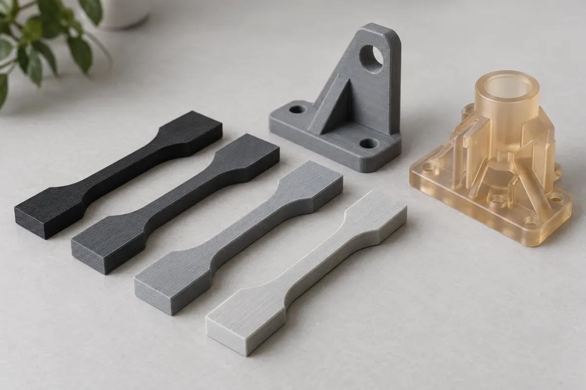
- If you want coupons, such as tensile bars, built with the part, upload them as parts with the same material, orientation and settings. Whether printed coupons represent your part is a decision for your test plan, and D638's note on preparation applies to them too.
Revision Control
- Put the part number and revision in the file name and on the drawing, and quote the same revision on the purchase order.
- Keep each test lot to one revision. Parts from two revisions in one test answer neither question.
- Treat a design change as a new file: upload the new revision and quote it, rather than describing the change in a note.
- Keep the quote reference with the test record, so the specification that was built can be traced. A CAD review before printing catches file problems before they become test variables.
Specification Checklist
Copy the rows that apply into a drawing note or the purchase order. The examples are hypothetical.
| Item | What to state | Hypothetical example |
|---|---|---|
| Part ID | Part number, revision, file | BRK-104 rev C, STEP |
| Process | FDM or SLA | FDM |
| Material | Catalog grade name | PA12-CF |
| Color | Same for all builds | Black |
| Orientation | Load direction vs build axes | Load in the layer plane |
| Layer height | Only if the test depends on it | As quoted, constant |
| Walls and infill | FDM only, if it matters | 100% infill |
| Critical dimensions | Feature, nominal, tolerance | Bore B1 8.0 ±0.2 mm |
| Finishing | Per surface, or as printed | As printed |
| Conditioning | State at test, standard, who | Tester, per ASTM D618 |
| Inspection | Features, method, who | Customer checks B1 |
| Quantity | Test articles plus spares | 6 plus 2 spares |
| Revision rule | What a change means | New file, new quote |
A Drawing Note, Written Out
Hypothetical example for a bracket tested in tension. Adapt the wording to your drawing format:
- PROCESS: FDM. MATERIAL: PA12-CF, black.
- ORIENTATION: tensile load along part X, in the layer plane. No layer boundary may run across section A-A.
- BUILD: 100% infill. Other settings as quoted, identical for all units.
- CRITICAL: bore B1 8.0 mm ±0.2 mm, measured by customer on receipt.
- FINISH: as printed, support material removed.
- CONDITION: conditioned by customer per ASTM D618 before test.
- REVISION: BRK-104 rev C. All units from one revision.
Frequently asked questions
Will a printed part match the material's datasheet?
Do you validate or test the parts?
Which build orientation should I specify?
Should nylon test parts be conditioned before testing?
Can I order test coupons with my parts?
Can I change the design between test rounds?
Sources
- ASTM: D638-22 Standard Test Method for Tensile Properties of Plastics
- ASTM: F2971-13(2021) Standard Practice for Reporting Data for Test Specimens Prepared by Additive Manufacturing
- SIS (Swedish Institute for Standards): SS-EN ISO 17295:2023 Additive manufacturing, part positioning, coordinates and orientation
- ASTM: D618-21 Standard Practice for Conditioning Plastics for Testing
- SIS (Swedish Institute for Standards): SS-EN ISO 1110:2019 Polyamides, accelerated conditioning of test specimens
- NIST: Thermography and Weld Strength Characterization of Thermoplastic Extrusion 3D Printing
- Texas State University (Solid Freeform Fabrication Symposium 2016): Tensile, compressive and flexural properties of printed ABS by printing orientation
- Polymaker: PolyMide PA6-CF technical data sheet (V5)
- Polymers (2025, via PMC): Effects of Post-Curing on Mechanical Strength and Cytotoxicity of Stereolithographic Methacrylate Resins
- SPIROL: How to Select a Threaded Insert for Your 3D Printed Assembly (white paper)
Send your test spec with your files
Upload your parts and include the specification your test depends on: material grade, orientation, settings, finishing and revision. Ask for a free printability review before you order.
Upload your files