Snap Fits, Press Fits, and Clearances for 3D Printed Assemblies
Starting points for snap-fit arms, press fits and sliding clearances in FDM and SLA parts, how tolerances stack up, and why one fit-check sample comes first.
The Short Answer
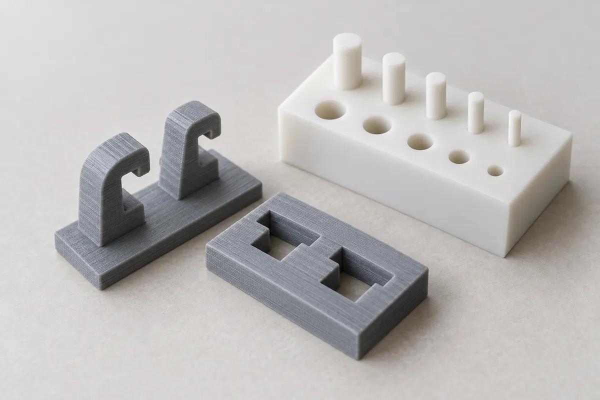
No single clearance works for every printed fit. Start from the process tolerance (FDM ±0.2 mm and SLA ±0.1 mm as general guidance), add up how those variations stack across the mating features, size snap-fit arms from the material's strain limit in the direction they bend, and treat any press fit as a value you tune. Then print one fit-check sample in the real process, material and orientation before you order more.
Why Printed Fits Need Their Own Numbers
Most published fit tables were written for machined metal and molded plastic. Printed parts differ in two ways that matter. Their dimensions vary within the process tolerance, and FDM parts are not equally strong in every direction: a 2021 review of anisotropy in printed polymers reports that FDM's direction dependence can reach almost 50%, against around 1% for SLA. Hole sizes are not predictable from a rule of thumb either. A university study of PLA parts measured printed holes larger than modeled, while earlier work it cites found printed holes consistently undersized. Machine, material and settings decide the direction, which is why every number in this guide is a starting point to verify.
How Tolerances Stack in an Assembly
Every fit is a chain of dimensions. A pin in a hole has two links; a lid that locates on a frame that sits on a base has more. Worst-case analysis adds the tolerances. Statistical (root-sum-square) analysis adds them in quadrature. In Daniel Whitney's MIT assembly course notes, worst-case error grows in step with the number of parts, while statistical error grows with its square root, but only when the parts are centered on nominal.
| Chain | Worst case | Root-sum-square |
|---|---|---|
| Two FDM dimensions (±0.2 mm) | ±0.4 mm | about ±0.28 mm |
| Two SLA dimensions (±0.1 mm) | ±0.2 mm | about ±0.14 mm |
| One FDM, one SLA | ±0.3 mm | about ±0.22 mm |
| Three FDM dimensions | ±0.6 mm | about ±0.35 mm |
Centered or Offset
Printed features are often not centered on nominal. On a given setup a hole can run consistently small or consistently large. That offset is what a fit-check sample measures, and once you know it you can design it out of the CAD. The root-sum-square column only describes the scatter that remains after the offset is removed, so do not design to it from the start. More on where variation comes from is in tolerances and accuracy.
Clearance Starting Points for Sliding and Rotating Fits
For a pin and hole to assemble every time, the diametral clearance has to cover the worst case of both features. With the general tolerances above, that gives the starting points below. They come from arithmetic on the published tolerances, not from a test of your material, and they are the first value to try, not a guaranteed fit.
| Mating features | Start at (on diameter) | Why |
|---|---|---|
| FDM pin in FDM hole | 0.4 mm | Both can vary ±0.2 mm |
| SLA pin in SLA hole | 0.2 mm | Both can vary ±0.1 mm |
| FDM and SLA mixed | 0.3 mm | ±0.2 mm plus ±0.1 mm |
| Metal pin in FDM hole | 0.2 mm + pin tolerance | Mostly the hole varies |
| Metal pin in SLA hole | 0.1 mm + pin tolerance | Mostly the hole varies |
Running Fits Need More
A part that has to slide or turn freely, rather than just go together, needs room beyond these figures for friction and surface texture. Start at or above the worst-case value, print the sample, and tighten only if the fit is loose. Orient a precise round bore with care, because a hole lying on its side is built from stepped layers while one standing upright is built from stacked circles. Orientation is one of the things our free printability review checks.
Press Fits: Tune Them, Do Not Trust Them
A press fit holds by interference, and printed tolerances are large compared with typical interference. DuPont's design guide shows molded examples at interferences of 1% and 4% of diameter. On a 10 mm pin that is 0.1 to 0.4 mm, while two FDM features can each vary by ±0.2 mm. A press fit drawn from nominal dimensions can come out loose on one print and split the socket on the next.
- Tune the interference with a fit-check sample in the real process and material, then adjust the CAD.
- Let the socket flex. DuPont uses slots to allow deeper snap-fit undercuts at some cost in retaining force, and a slotted or split socket accepts printed variation the same way.
- Expect relaxation. DuPont notes that plastic creeps and stress-relaxes under a press fit, so some loosening should be expected. Knurls or grooves on the pin let the plastic flow into them and keep its grip, and DuPont advises testing at the temperatures the part will see.
- Do not rely on interference alone for torque. DuPont advises interference fits for gears only when torque is low, because stress relaxation can let them slip.
- Watch dissimilar materials. Different thermal expansion changes the interference as temperature changes, per DuPont.
- For a joint that must stay put, a heat-set insert or a fastener is often more predictable. See heat-set inserts and threads.
Designing a Snap-Fit Arm
The polymer makers' guides size a snap arm from strain, not force. The undercut is the deflection the arm has to make, and it must make it without exceeding the material's permissible strain at the root, where arms fail.
- Taper the arm. Bayer's snap-fit guide (Bayer MaterialScience is now Covestro) recommends thinning the arm linearly to half its root thickness at the hook, which allows more than 60% more deflection than a constant-thickness arm. For that tapered rectangular arm, deflection y = 1.09 × ε × l² ÷ h, where l is the arm length, h the root thickness and ε the permissible strain as a decimal.
- Length is the strongest lever. At the same strain, doubling the length gives four times the deflection; halving the root thickness gives twice.
- Round the root. DuPont's formulas use a stress concentration factor of 1.0 for a filleted root and 2.0 for a poorly rounded corner. Bayer finds the benefit of a larger radius levels off near a radius of 0.6 times the arm thickness, and limits it in molded parts only because thick molded sections sink.
- Shape the hook. In DuPont's guide a 30° lead-in eases assembly, a 45° return angle is satisfactory for most joints that must come apart, and a 90° return angle makes a permanent joint.
- Budget for reuse. Bayer advises using about 60% of the one-time strain limit for joints that are separated and rejoined often.
- Share the deflection. Bayer's equations assume the mating part is rigid; when both parts flex about equally, each takes about half the undercut.
- Expect friction. Mating force rises with friction and lead angle, and Bayer notes that two parts of the same plastic generally have higher friction than two different plastics.
A Worked Snap-Fit Example
Hypothetical example: a tapered arm 12 mm long and 1.6 mm thick at the root, with a strain budget of 1.5%, can deflect about 1.09 × 0.015 × 144 ÷ 1.6, or roughly 1.5 mm, so its hook can engage an undercut of about that depth. The 1.5% is illustrative and is not a value for any material we print. Your strain budget has to come from the material's data in the direction the arm bends, and from a test.
Where the Strain Budget Comes From
Bayer's guide lists permissible short-term strain for its molded resins in a single assembly, for example 4% for Makrolon polycarbonate and 2.5% for Bayblend PC/ABS. DuPont's table shows glass-reinforced nylon allowing a fraction of the strain of unfilled nylon, and nylon's allowance changing between dry and humid conditions. Those are molded values. A printed arm can be much weaker in one direction: Forward AM's typical values for its Ultrafuse ABS filament list an elongation at break of 7.4% along the layers (XY) and 1.8% across them (ZX). Layer direction alone changed the strain that grade survives by about four times.
- In FDM, orient snap arms so they bend within the layers, never so the layers peel apart.
- In FDM, start with the plastics the snap-fit guides are written around: polycarbonate, PC-ABS, ABS and nylon such as PA12. TPU 64D suits semi-rigid clips that bend rather than stretch.
- Test any fiber-filled grade, such as PA6-CF, before relying on it for a snap arm; the filled molded grades in DuPont's table allow far less strain.
- Nylon changes with moisture. See nylon dimensions and moisture conditioning.
- In SLA, which is close to the same strength in every direction, choose a resin made for repeated strain, such as Tough Resin or Durable Resin, rather than Standard Resin.
FDM and SLA Behave Differently
Mixing the two is often the best answer, such as an FDM housing with an SLA latch. Each part is priced and sized by its own process; see mixing FDM and SLA in one order, and the FDM and SLA service pages.
| Behavior | FDM | SLA |
|---|---|---|
| General tolerance | ±0.2 mm | ±0.1 mm |
| Strength by direction | Weaker across layers | Close to equal in all directions |
| Snap arms | Bend within the layers | Tough or Durable Resin |
| Threaded inserts | Heat-set inserts | Press-in or self-tapping inserts |
| Press fits | Tune by test; expect relaxation | Tune by test |
Test the Fit With One Sample First
Before ordering a batch, order one set, or a small coupon of just the mating features, in the same process, material and orientation as the real part. Measure it, assemble it, and adjust the CAD. The manufacturers' guides say the same in their own words: SPIROL recommends refining insert hole size over several prints, and DuPont recommends tests on prototype parts when friction matters.
- Include each interface: pin and hole, snap arm and catch, press-fit pin and socket.
- Print two or three variants of the critical clearance or interference side by side, each labeled, so one sample brackets the right value.
- Keep the same wall thickness around each feature as the real part, because a thinner socket flexes more.
- Once the fit is right, order the quantity you need on the quote page; quantity pricing tiers are applied automatically.
Frequently asked questions
What clearance should I use for 3D printed parts that slide together?
Can I press-fit a bearing into a 3D printed part?
Should a snap fit be printed in FDM or SLA?
How many times can a printed snap fit be opened and closed?
Why does a fit that worked in one material fail in another?
Sources
- Bayer MaterialScience (now Covestro): Snap-Fit Joints for Plastics, A Design Guide (copy hosted by MIT)
- DuPont: General Design Principles for DuPont Engineering Polymers (Design Guide Module I)
- MIT OpenCourseWare, Daniel E. Whitney: Variation Buildup in Assemblies-2 (2.875)
- Zohdi and Yang, Polymers (2021): Material Anisotropy in Additively Manufactured Polymers and Polymer Composites: A Review
- Forward AM: Ultrafuse ABS (typical properties)
- ASEE 2024, Southeastern Louisiana University: Preliminary Investigation of Dimensional Accuracy of 3D Printed PLA
- SPIROL: How to Select a Threaded Insert for Your 3D Printed Assembly
- Pagac et al., Polymers (2021): A Review of Vat Photopolymerization Technology
Order a fit-check sample
Upload the mating parts, or a coupon of just the interfaces, in the process and material you plan to use. One sample shows how your fits print before you order the batch.
Upload your fit-check parts